README
Apollo Landing Site Terrain Survey
experimentNo. 0061categoryRides & explorationrecordingpendingdataCC BY 4.0
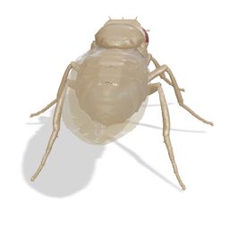
The fly, enlarged to about 7 m, traverses stereo-derived Lunar Reconnaissance Orbiter terrain at Apollo landing sites, stopping at published positions of the lunar module, surface experiments and nearby craters.
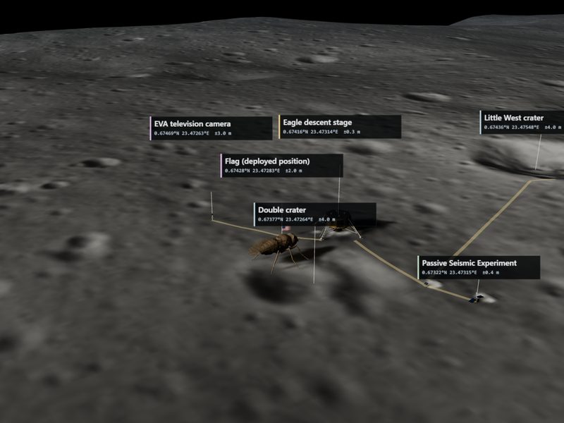
Recording pending publication. Follow along for the release.
Setup
- Two configured sites: Apollo 11 Tranquility Base (six survey stops) and Apollo 15 Hadley–Apennine (five survey stops, including the Hadley Rille rim and floor).
- Terrain comes from LROC NAC stereo elevation models and aligned orthoimages; one scene unit equals 10 terrain metres, with no vertical exaggeration.
- Guided survey tour or manual traverse with W/A/S/D, turn and 10 m advance controls; speeds of 2, 5, 10, 25 or 50 m/s.
- Landing site, Follow fly, Surface eye, Survey and Topography cameras, with optional labels and schematic EVA path ribbons.
- A comparison control switches to the separate Apollo studio-set scene; that studio setting is modeled without a documented source.
Measurement
- Optional live neural input submits the canonical eye image's 32 luminance columns to the fixed connectome model; weights are not updated.
- Navigation and gait are pre-programmed; measured spikes do not steer the survey.
- Packages save the site and traverse settings, not a learned skill.
Limitations
- Hardware models are procedural approximations placed at positions from the LROC anthropogenic-object table (Wagner et al. 2017); the Apollo 11 TV camera and flag are reconstructed from ALSJ distances.
- Amber ribbons are schematic EVA paths, not digitized footprints.
- The orthoimage carries the illumination of the orbital image, not of the Apollo surface activities.
- The fly is enlarged for legibility; the Apollo 15 lunar module heading is approximate, not measured.